The Athabasca Oil Sands Project (AOSP) is a joint venture between majority owner Shell Canada, Chevron Canada, and Marathon Oil Canada Corporation. AOSP operates two mines. No processing is done at the mines and the bitumen is transported in a diluted form by pipeline to the Scotford upgrader facility located 50 km northeast of Edmonton, Alberta. The Scotford upgrader currently produces 255,000 barrels per day of synthetic crude. This currently meets 10% of Canada’s requirements.
The proposed Keystone XL pipeline, to transport Alberta oil down to refineries on the Gulf of Mexico ignited a firestorm of controversy, and it was eventually blocked by President Obama. Critics claim it encourages the use of “dirty” oil. (Until recently, Canadian oil supplied 17% of US demand, the tar sands have been actively mined since the mid-60’s.) The critics have several complaints, but a significant fact is that in “upgrading” the bitumen, large quantities of CO2 are generated.
Shell Canada is investing $1.4 billion in the Quest carbon capture and storage demonstration project. It is designed to capture one million tonnes of CO2 annually from the company’s Scotford heavy oil upgrader. The CO2 is converted from a gas to liquid, and transported by a new 60 km pipeline to a storage site. To put this in perspective, one million tonnes of carbon dioxide is equivalent to the annual tailpipe emissions of 175,000 cars. The Government of Canada and the province of Alberta are also providing funding for this initiative.
Gas and oil are typically extracted from deposits trapped by stone formations below the earth’s surface. In a novel twist, captured CO2 will be injected into a sandstone formation, two kilometers down. The CO2 is injected under pressure into the porous sandstone geological formation. Once injected, the CO2 moves through the formation, but is trapped by an impermeable layer of cap rock overlying the sandstone storage. This method of storing (sequestering) carbon dioxide is termed “structural storage”. There is considerable experience with Carbon Capture and Sequestration (CSS) projects worldwide and the evidence is that carbon dioxide can be captured permanently in geological formations. For example, the Norwegian Sleipner project, operating since 1996, has stored CO2 which is injected into oil wells to enhance oil recovery at this offshore oil fields. Impermeable geologic formations have trapped oil and gas for millions of years, which provides confidence that carbon dioxide will be safely stored indefinitely. Three sealing layers of rock exist at the Quest storage site. Shell has decades of experience in modeling subsurface geologic formations during gas exploration, providing the company with unique expertise in storage site selection.
One process used to upgrade the bitumen to lighter synthetic oil involves hydrocracking where steam, methane gas, and a catalyst are combined with the bitumen under high pressure. The chemical reaction produces hydrogen, which is then used to convert the heavy oil into lighter crude by a process called “hydrogen addition”. But carbon dioxide is a byproduct of the process. The Scotford upgrader currently releases three million tonnes annually into the atmosphere.
The Quest facility pipes CO2 gas into a vessel containing Shell’s patented ADIP-X amino-based capture technology, which absorbs the CO2. The solution is then piped to a stripping tower where heat and pressure release the CO2, which is then piped to a compressor station. The compressor turns the gas to a liquid that can be transported by pipeline.
Pipeline Construction
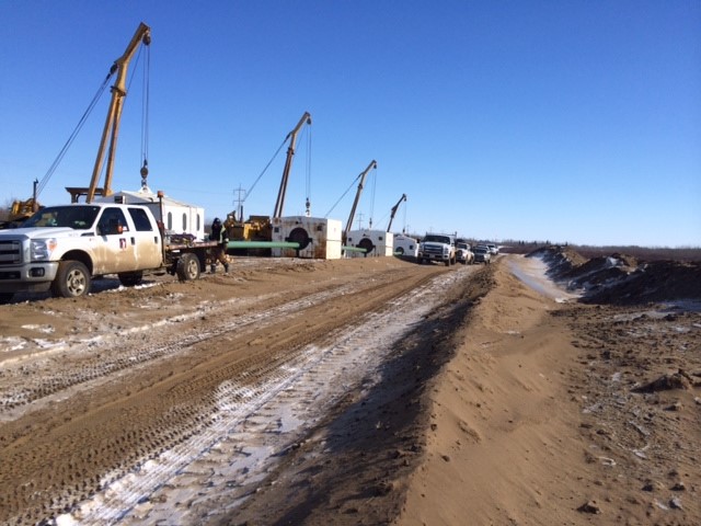
The construction of the 60 km 12” pipeline posed significant challenges. Because the pipeline would be transporting liquid CO2, the welds had to meet Charpy impact testing of 60 joules at -50⁰ C as pipeline construction for this project was generally through farmland, with several marshy areas. Work was done through a winter ith temperatures reaching down to -30⁰C.
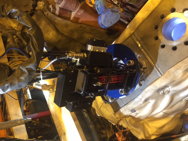
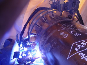
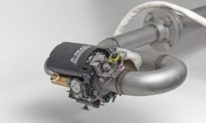
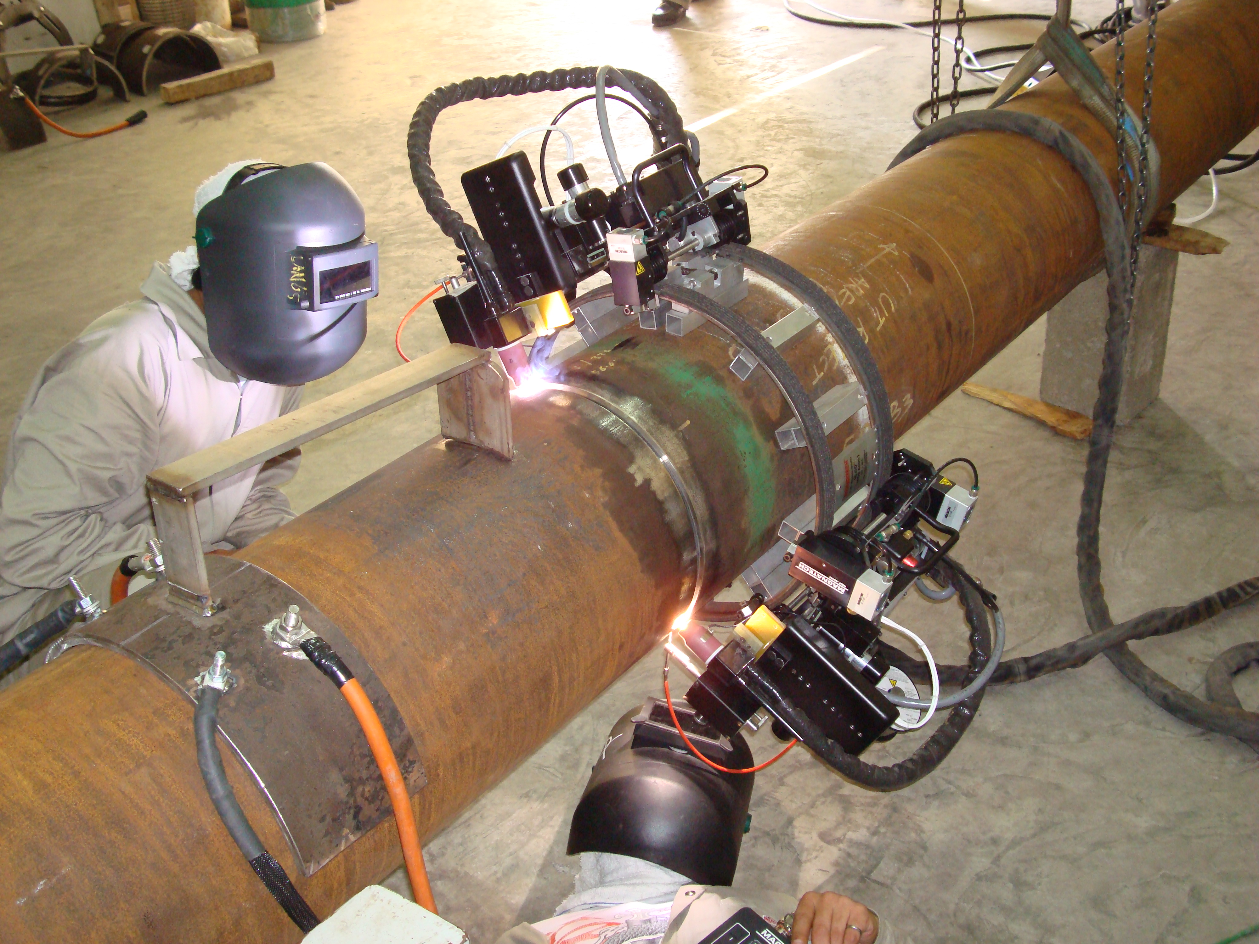
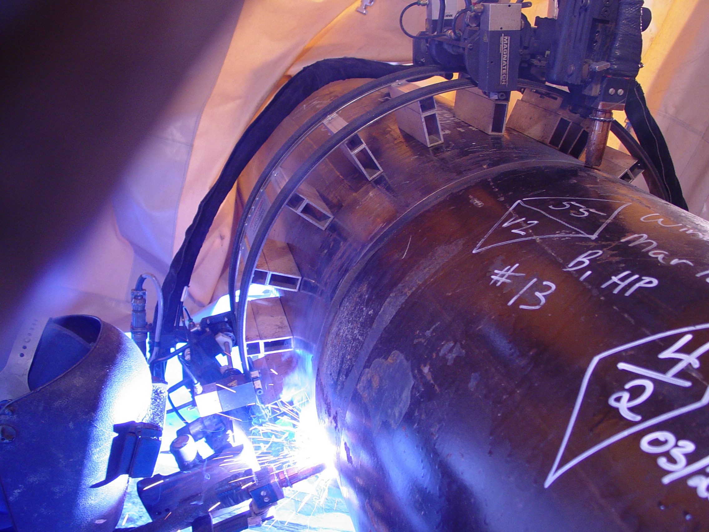
Shell contracted with Aecom Technology’s Flint division (formerly Flint Energy Services Ltd.) for the pipeline project. A standard 30⁰ bevel was used as delivered from the mill. A gap was maintained between pipe ends, and a 1.6 m land was used. The root and hot pass were done using 8010 electrodes welding double down. Two additional fill passes and a cap pass were made using the flux-cored process. The contractor used Magnatech Pipeliner FCAW systems based on prior experience renting from John W. Page Welding Consulting. John also provided his experience and technical support during the project. The fill and cap passes were carried out using the Magnatech Pipeliner. The Magnatech Pipeliner is a “bug and band” type system. A guide ring is first mounted on the pipe and the weld Head is quickly installed on the guide ring using a push button switch. Welding is carried out in a double-up progression. The welder starts the weld at six o’clock and welds clockwise to 12 o’clock. The Head is declutched and rapidly repositioned to six o’clock and the pass completed welding to 12 o’clock in the counterclockwise direction.
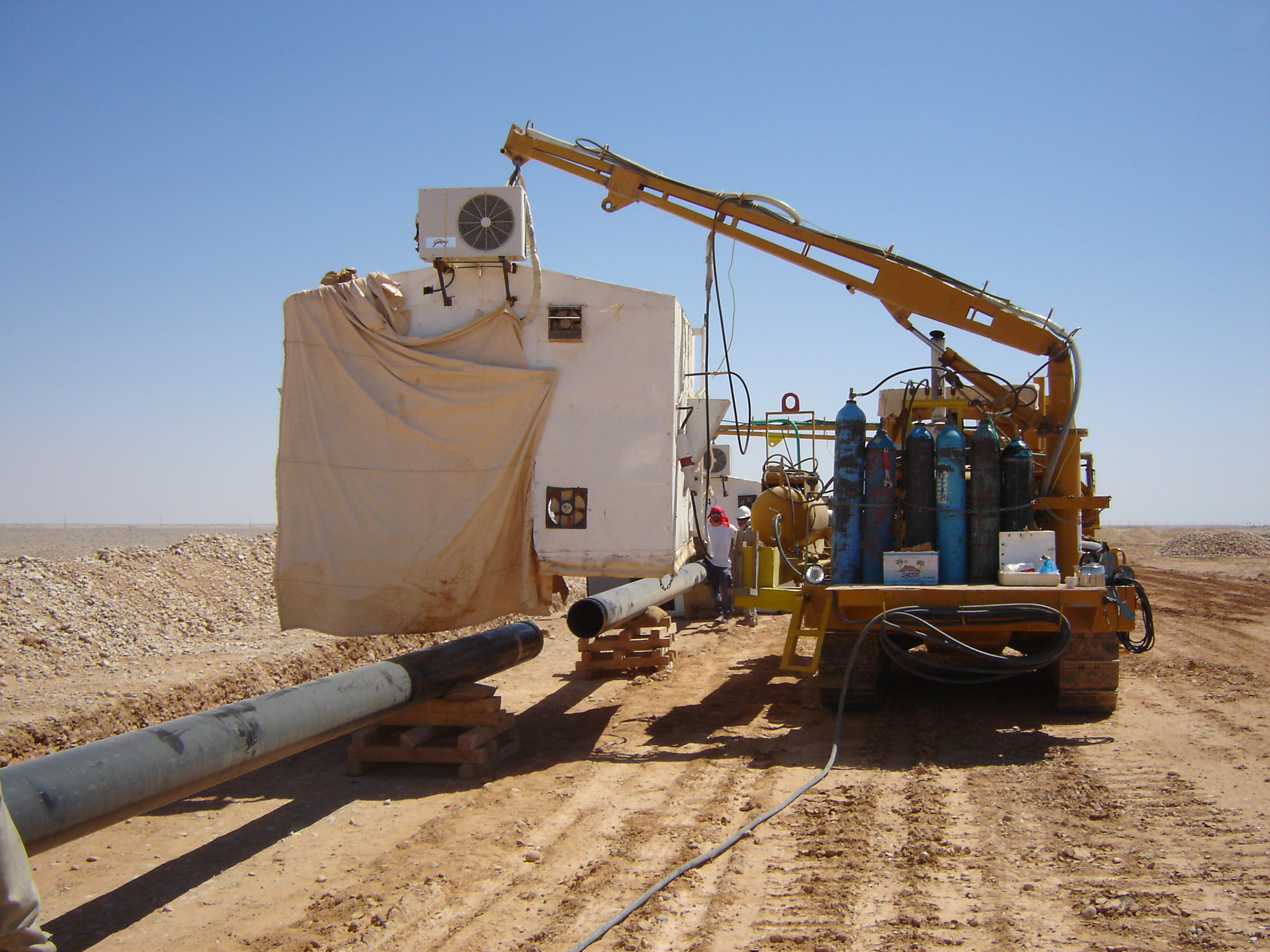
A side boom mounting on a diesel generator, lowered the tent over the joint. The Pipeliner power supply, water recirculator, and gas bottle were mounted on a steel plate attached to the tent frame. The entire welding system was contained in the tent, with only a power cable from the generator required.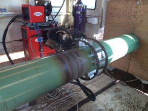
Hobart Brothers’ Corex filler wire was used on the 12 in. pipe, 1.3 mm diameter alloy E71T-9. For the 12 in. X-80 pipe, filler wires used were Lincoln Pipeliner G-80M (E101T1-GM-H8) and the ESAB Dual Shield II 101-TC (E80T-a-K2). A mixed gas of 75% Argon, 25% CO2 was used. A preheat of at least 100⁰ C was required. Although two weld heads can be simultaneously used for welding a pipe joint, the small diameter 12” pipe made it less practical for more than one bug on a pipe. Typical time for the six passes was between 53 – 62 minutes, substantially less than manual welding.
The pipe material was specified to meet the low temperature toughness requirements for liquid carbon dioxide transmission. During procedure testing, it became evident that to achieve the requisite mechanical properties in both the weld metal and Heat Affected Zone (HAZ) that mechanized welding was required. The uniform torch rotation speed prevented variations in heat input. Manual welding with semiautomatic FCAW torches had consistently failed testing in the HAZ.
“Tie in” welds at river or road crossings required welding to an existing pipeline that is already strung beneath the obstacle and often has a heavier wall thickness. Tie in welds required welding to the existing string in the ditch. The welding system and tent were lowered into the ditch to perform the welds. A total of ten systems were used, with several tie in crews.
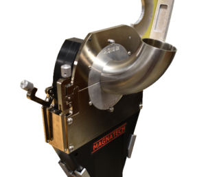

 delivered five ID welders to a contractor specializing in reworking critical valves used in electrical power plants.